

Self Induction
- Availibility: In Stock
Components Required:
- Inductor (Coil with known inductance, e.g., 100mH or 1H)
- Variable Power Supply (DC source for current control, e.g., 12V DC power supply)
- Switch (To control the current flow)
- Resistor (To limit current and measure voltage, e.g., 100Ω)
- Oscilloscope (For visualizing voltage changes over time)
- Multimeter (For measuring voltage, current, and resistance)
- Connecting Wires
- Baseboard (Optional, for mounting components)
- Capacitor (Optional, for smoothing the signal if needed)
Qty
Your Transaction is Secure
We work hard to Protect your Security and Privacy. Our Payment Security System Encrypts your information during transmission.
Description
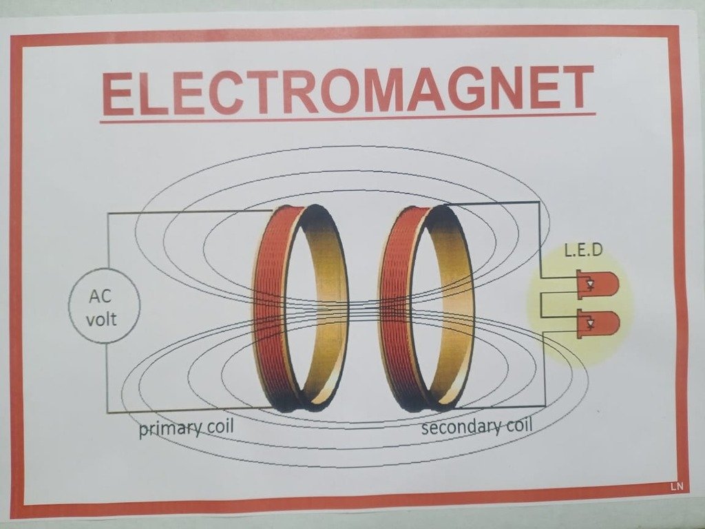
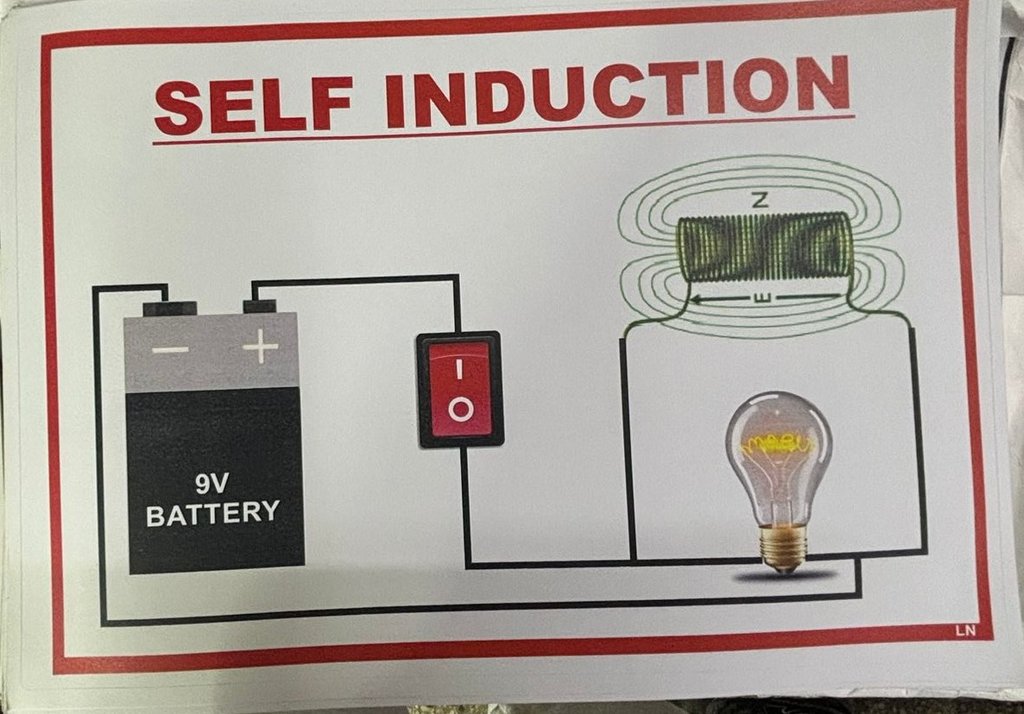
Project Description: This project involves setting up a circuit with an inductor, a power supply, a switch, and a resistor. The circuit is designed to observe the effects of self-induction when the current through the inductor is changed.
Students will connect the inductor in series with a resistor and a switch to the power supply. When the switch is closed, current flows through the inductor, and the rate of change of current is controlled. By observing the induced voltage across the resistor using an oscilloscope, students can analyze how the self-induced voltage varies with the rate of change of current.
The project demonstrates the concept of self-inductance and provides practical experience with measuring and interpreting inductive effects in a circuit.
Applications:
- Understanding the concept of self-induction and inductance
- Observing the relationship between changing current and induced voltage
- Practical experience with oscilloscopes and multimeters in measuring electrical phenomena
- Educational tool for learning about electromagnetic induction and its applications
Additional information
Reviews
Add a Review
Your email address will not be published. Required fields are marked *


