Half Wave Rectifier
- Availibility: In Stock
Components Required:
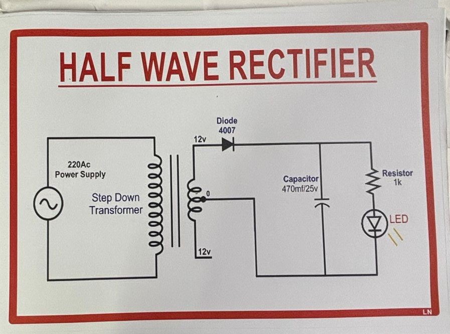
- Transformer (Optional, to step down AC voltage if needed, e.g., 230V to 12V AC)
- Diode (e.g., 1N4007 or similar for rectification)
- Load Resistor (To simulate a load, e.g., 1kΩ)
- Capacitor (Optional, for smoothing the DC output, e.g., 100µF)
- AC Power Source (e.g., AC adapter or signal generator)
- Oscilloscope (For visualizing the input and output waveforms)
- Multimeter (For measuring voltage and current)
- Connecting Wires
- Baseboard (Optional, for mounting components)
Qty
Your Transaction is Secure
We work hard to Protect your Security and Privacy. Our Payment Security System Encrypts your information during transmission.

Description
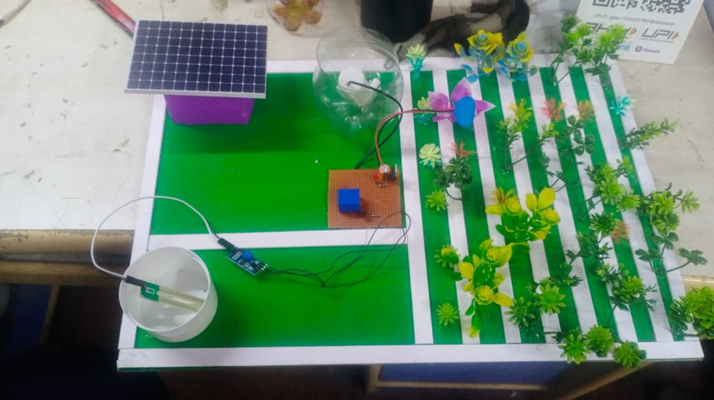
Project Description: This project involves constructing a half-wave rectifier circuit using a diode to convert AC voltage to pulsating DC voltage. The circuit can be built with or without a transformer, depending on the input AC voltage requirements.
Students will connect the AC power source to the primary side of the transformer (if used) and the secondary side to the diode. The diode is connected in series with the load resistor. If a capacitor is included, it is connected across the load resistor to smooth the output.
By measuring the input and output voltages with an oscilloscope and multimeter, students can analyze the rectification process, observe the waveform changes, and calculate the efficiency of the rectifier. The project demonstrates the principles of rectification, including the function of the diode and the effect of smoothing capacitors.
Additional information
Reviews
Add a Review
Your email address will not be published. Required fields are marked *